In this tutorial, you will learn how to get and set pixel values using OpenCV and Python.

You will also learn:
- What pixels are
- How the image coordinate system works in OpenCV
- How to access/get individual pixel values in an image
- How to set/update pixels in an image
- How to use array slicing to grab regions of an image
By the end of this tutorial, you will have a strong understanding of how to access and manipulate pixels in an image using OpenCV.
To learn how to get and set pixels with OpenCV, just keep reading.
OpenCV Getting and Setting Pixels
In the first part of this tutorial, you will discover what pixels are (i.e., the building blocks of an image). We’ll also review the image coordinate system in OpenCV, including the proper notation to access individual pixel values.
From there, we’ll configure our development environment and review our project directory structure.
With our project directory structure reviewed, we’ll implement a Python script, opencv_getting_setting.py. As the name suggests, this allows us to access and manipulate pixels using OpenCV.
We’ll wrap up this tutorial with a discussion of our results.
Let’s get started!
What are pixels?
Pixels are the raw building blocks of an image. Every image consists of a set of pixels. There is no finer granularity than the pixel.
Normally, a pixel is considered the “color” or the “intensity” of light that appears in a given place in our image.
If we think of an image as a grid, each square in the grid contains a single pixel. Let’s look at the example image in Figure 1:

Most pixels are represented in two ways:
- Grayscale/single channel
- Color
In a grayscale image, each pixel has a value between 0 and 255, where 0 corresponds to “black” and 255 being “white.” The values between 0 and 255 are varying shades of gray, where values closer to 0 are darker and values closer 255 are lighter:

The grayscale gradient image in Figure 2 demonstrates darker pixels on the left-hand side and progressively lighter pixels on the right-hand side.
Color pixels, however, are normally represented in the RGB color space — one value for the Red component, one for Green, and one for Blue leading to a total of 3 values per pixel:

Other color spaces exist (HSV (Hue, Saturation, Value), L*a*b*, etc.), but let’s start with the basics and move our way up from there.
Each of the three Red, Green, and Blue colors are represented by an integer in the range from 0 to 255, which indicates how “much” of the color there is. Given that the pixel value only needs to be in the range [0, 255], we normally use an 8-bit unsigned integer to represent each color intensity.
We then combine these values into an RGB tuple in the form (red, green, blue). This tuple represents our color.
To construct a white color, we would completely fill each of the red, green, and blue buckets, like this: (255, 255, 255) — since white is the presence of all colors.
Then, to create a black color, we would completely empty each of the buckets: (0, 0, 0) — since black is the absence of color.
To create a pure red color, we would completely fill the red bucket (and only the red bucket): (255, 0, 0).
Are you starting to see a pattern?
Look at the following image to make this concept more clear:

In the top-left example, we have the color white — each of the Red, Green, and Blue buckets have been completely filled to form the white color.
And on the top-right, we have the color black — the Red, Green, and Blue buckets are now totally empty.
Similarly, to form the color red in the bottom-left, we simply fill the Red bucket completely, leaving the other Green and Blue buckets totally empty.
Finally, blue is formed by filling only the Blue bucket, as demonstrated in the bottom-right.
For your reference, here are some common colors represented as RGB tuples:
- Black:
(0, 0, 0) - White:
(255, 255, 255) - Red:
(255, 0, 0) - Green:
(0, 255, 0) - Blue:
(0, 0, 255) - Aqua:
(0, 255, 255) - Fuchsia:
(255, 0, 255) - Maroon:
(128, 0, 0) - Navy:
(0, 0, 128) - Olive:
(128, 128, 0) - Purple:
(128, 0, 128) - Teal:
(0, 128, 128) - Yellow:
(255, 255, 0)
Now that we have a good understanding of pixels let’s have a quick review of the coordinate system.
Overview of the image coordinate system in OpenCV
As I mentioned in Figure 1, an image is represented as a grid of pixels. Imagine our grid as a piece of graph paper. Using this graph paper, the point (0, 0) corresponds to the top-left corner of the image (i.e., the origin). As we move down and to the right, both the x and y-values increase.
Let’s look at the image in Figure 5 to make this point more clear:

Here, we have the letter “I” on a piece of graph paper. We see that we have an 8 x 8 grid with 64 total pixels.
The point at (0, 0) corresponds to the top-left pixel in our image, whereas the point (7, 7) corresponds to the bottom-right corner.
It is important to note that we are counting from zero rather than one. The Python language is zero-indexed, meaning that we always start counting from zero. Keep this in mind, and you will avoid a lot of confusion later on.
Finally, the pixel 4 columns to the right and 5 rows down is indexed by the point (3, 4), keeping in mind that we are counting from zero rather than one.
Configuring your development environment
To follow this guide, you need to have the OpenCV library installed on your system.
Luckily, OpenCV is pip-installable:
$ pip install opencv-contrib-python
If you need help configuring your development environment for OpenCV, I highly recommend that you read my pip install OpenCV guide — it will have you up and running in a matter of minutes.
Having problems configuring your development environment?
All that said, are you:
- Short on time?
- Learning on your employer’s administratively locked system?
- Wanting to skip the hassle of fighting with the command line, package managers, and virtual environments?
- Ready to run the code right now on your Windows, macOS, or Linux system?
Then join PyImageSearch Plus today!
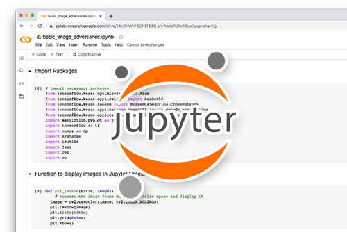
Gain access to Jupyter Notebooks for this tutorial and other PyImageSearch guides that are pre-configured to run on Google Colab’s ecosystem right in your web browser! No installation required.
And best of all, these Jupyter Notebooks will run on Windows, macOS, and Linux!
Project structure
Before we start looking at code, let’s review our project directory structure:
$ tree . --dirsfirst
.
├── adrian.png
└── opencv_getting_setting.py

0 directories, 2 files
We have a single Python script to review today, opencv_getting_setting.py, which will allow us to access and manipulate the image pixels from the image adrian.png.
Getting and setting pixels with OpenCV
Let’s learn how to get and set pixels with OpenCV.
Open the opencv_getting_setting.py file in your project directory structure, and let’s get to work:
# import the necessary packages
import argparse
import cv2

# construct the argument parser and parse the arguments
ap = argparse.ArgumentParser()
ap.add_argument("-i", "--image", type=str, default="adrian.png",
	help="path to the input image")
args = vars(ap.parse_args())
Lines 2 and 3 import our required Python packages. We only need argparse for our command line arguments cv2 for our OpenCV bindings.
The --image command line argument points to the image we want to manipulate residing on disk. By default, the --image command line argument is set to adrian.png.
Next, let’s load this image and start accessing pixel values:
# load the image, grab its spatial dimensions (width and height),
# and then display the original image to our screen
image = cv2.imread(args["image"])
(h, w) = image.shape[:2]
cv2.imshow("Original", image)
Lines 13-15 load our input image from disk, grab its width and height, and displays the image to our screen:

Images in OpenCV are represented by NumPy arrays. To access a particular image pixel, all we need to do is pass in the (x, y)-coordinates as image[y, x]:
# images are simply NumPy arrays -- with the origin (0, 0) located at
# the top-left of the image
(b, g, r) = image[0, 0]
print("Pixel at (0, 0) - Red: {}, Green: {}, Blue: {}".format(r, g, b))

# access the pixel located at x=50, y=20
(b, g, r) = image[20, 50]
print("Pixel at (50, 20) - Red: {}, Green: {}, Blue: {}".format(r, g, b))

# update the pixel at (50, 20) and set it to red
image[20, 50] = (0, 0, 255)
(b, g, r) = image[20, 50]
print("Pixel at (50, 20) - Red: {}, Green: {}, Blue: {}".format(r, g, b))
Line 19 accesses the pixel located at (0, 0), which is the top-left corner of the image. In return, we receive the Blue, Green, and Red intensities (BGR), in that order.
The big question is:
Why does OpenCV represent images in BGR channel ordering rather than the standard RGB?
The answer is that back when OpenCV was originally developed, BGR ordering was the standard! It was only later that the RGB order was adopted. The BGR ordering is standard in OpenCV, so get used to seeing it.
Line 23 then accesses the pixel located at x = 50, y = 20 using the array indexing of image[20, 50].
But wait . . . isn’t that backward? Shouldn’t it instead be image[50, 20] since x = 50 and y = 20?
Not so fast!
Let’s back up a step and consider that an image is simply a matrix with a width (number of columns) and height (number of rows). If we were to access an individual location in that matrix, we would denote it as the x value (column number) and y value (row number).
Therefore, to access the pixel located at x = 50, y = 20, you pass the y-value first (the row number) followed by the x-value (the column number), resulting in image[y, x].
Note: I’ve found that the concept of accessing individual pixels with the syntax of image[y, x] is what trips up many students. Take a second to convince yourself that image[y, x] is the correct syntax based on the fact that the x-value is your column number (i.e., width), and the y-value is your row number (i.e., height).
Lines 27 and 28 update the pixel located at x = 50, y = 20, setting it to red, which is (0, 0, 255) in BGR ordering. Line 29 then prints the updated pixel value to our terminal, thereby demonstrating that it has been updated.
Next, let’s learn how to use NumPy array slicing to grab large chunks/regions of interest from an image:
# compute the center of the image, which is simply the width and height
# divided by two
(cX, cY) = (w // 2, h // 2)

# since we are using NumPy arrays, we can apply array slicing to grab
# large chunks/regions of interest from the image -- here we grab the
# top-left corner of the image
tl = image[0:cY, 0:cX]
cv2.imshow("Top-Left Corner", tl)
On Line 33, we compute the center (x, y)-coordinates of the image. This is accomplished by simply dividing the width and height by two, ensuring integer conversion (since we cannot access “fractional pixel” locations).
Then, on Line 38, we use simple NumPy array slicing to extract the [0, cX) and [0, cY) region of the image. In fact, this region corresponds to the top-left corner of the image! To grab chunks of an image, NumPy expects we provide four indexes:
- Start y: The first value is the starting y-coordinate. This is where our array slice will start along the y-axis. In our example above, our slice starts at y = 0.
- End y: Just as we supplied a starting y-value, we must provide an ending y-value. Our slice stops along the y-axis when y = cY.
- Start x: The third value we must supply is the starting x-coordinate for the slice. To grab the top-left region of the image, we start at x = 0.
- End x: Lastly, we need to provide the x-axis value for our slice to stop. We stop when x = cX.
Once we have extracted the top-left corner of the image, Line 39 shows the cropping result. Notice how our image is just the top-left corner of our original image:

Let’s extend this example a little further so we can get some practice using NumPy array slicing to extract regions from images:
# in a similar fashion, we can crop the top-right, bottom-right, and
# bottom-left corners of the image and then display them to our
# screen
tr = image[0:cY, cX:w]
br = image[cY:h, cX:w]
bl = image[cY:h, 0:cX]
cv2.imshow("Top-Right Corner", tr)
cv2.imshow("Bottom-Right Corner", br)
cv2.imshow("Bottom-Left Corner", bl)
In a similar fashion to the example above, Line 44 extracts the top-right corner of the image, Line 45 extracts the bottom-right corner, and Line 46 the bottom-left.
Finally, all four corners of the image are displayed on screen on Lines 47-49, like this:

Understanding NumPy array slicing is a very important skill that you will use time and time again as a computer vision practitioner. If you are unfamiliar with NumPy array slicing, I would suggest taking a few minutes and reading this page on the basics of NumPy indexes, arrays, and slicing.
The last task we are going to do is use array slices to change the color of a region of pixels:
# set the top-left corner of the original image to be green
image[0:cY, 0:cX] = (0, 255, 0)

# Show our updated image
cv2.imshow("Updated", image)
cv2.waitKey(0)
On Line 52, you can see that we are again accessing the top-left corner of the image; however, this time, we are setting this region to have a value of (0, 255, 0) (green).
Lines 55 and 56 then show the results of our work:

Figure 10: Setting the top-left corner of the image to be “green.”
OpenCV pixel getting and setting results
Let’s now learn how to get and set individual pixel values using OpenCV!
Be sure you have used the “Downloads” section of this tutorial to access the source code and example images.
From there, you can execute the following command:
$ python opencv_getting_setting.py --image adrian.png
Pixel at (0, 0) - Red: 233, Green: 240, Blue: 246
Pixel at (50, 20) - Red: 229, Green: 238, Blue: 245
Pixel at (50, 20) - Red: 255, Green: 0, Blue: 0
Once our script starts running, you should see some output printed to your console.
The first line of output tells us that the pixel located at (0, 0) has a value of R = 233, G = 240, and B = 246. The buckets for all three channels are nearly white, indicating that the pixel is very bright.
The next two lines of output show that we have successfully changed the pixel located at (50, 20) to be red rather than the (nearly) white color.
You can refer to the images and screenshots from the “Getting and setting pixels with OpenCV” section for the image visualizations from each step of our image processing pipeline.
What’s next?

Would you like to learn how to successfully and confidently apply OpenCV to your projects?
Are you worried that configuring your development environment for Computer Vision, Deep Learning, and OpenCV will be too challenging, resulting in confusing, hard to debug error messages?
Concerned that you’ll get lost sifting through endless tutorials and video guides on your own as you struggle to master Computer Vision?
Great, because I’ve got you covered. PyImageSearch University is your chance to learn from me at your own pace.
You’ll find everything you need to master the basics (like we did together in this tutorial) and move on to advanced concepts.
Don’t worry about your operating system or development environment. I’ve got you covered with pre-configured Jupyter Notebooks in Google Colab for every tutorial on PyImageSearch, including Jupyter Notebooks for our new weekly tutorials as well!
Best of all, these Jupyter Notebooks will run on your machine, regardless of whether you are using Windows, macOS, or Linux! Irrespective of the operating system used, you will still be able to follow along and run the code in every lesson (all inside the convenience of your web browser).
Additionally, you can massively accelerate your progress by watching our video lessons accompanying each post. Every lesson in PyImageSearch University includes a detailed, step-by-step video guide.
You may feel that learning Computer Vision, Deep Learning, and OpenCV is too hard. Don’t worry; I’ll guide you gradually through each lecture and topic, so we build a solid foundation, and you grasp all the content.
When you think about it, PyImageSearch University is almost an unfair advantage compared to self-guided learning. You’ll learn more efficiently and master Computer Vision faster.
Oh, and did I mention you’ll also receive Certificates of Completion as you progress through each course at PyImageSearch University?
I’m sure PyImageSearch University will help you master OpenCV drawing and all the other computer vision skills you will need. Why not join today?
Summary
In this tutorial, you learned how to get and set pixel values using OpenCV.
You also learned about pixels, the building blocks of an image, along with the image coordinate system OpenCV uses.
Unlike the coordinate system you studied in basic algebra, where the origin, denoted as (0, 0), is at the bottom-left, the origin for images is actually located at the top-left of the image.
As the x-value increases, we go farther to the right of the image. And as the y-value increases, we go farther down the image.
To download the source code to this post (and be notified when future tutorials are published here on PyImageSearch), simply enter your email address in the form below!
Download the Source Code and FREE 17-page Resource Guide
Enter your email address below to get a .zip of the code and a FREE 17-page Resource Guide on Computer Vision, OpenCV, and Deep Learning. Inside you'll find my hand-picked tutorials, books, courses, and libraries to help you master CV and DL!
The post OpenCV Getting and Setting Pixels appeared first on PyImageSearch.